Throughout the journey of amateur radio, enthusiasts often seek to push the boundaries of technology and creativity. One of the most fascinating aspects of this hobby is designing and installing antennas that not only perform well but also stand out as innovative, exceptional, or uniquely crafted. In this article, we delve into the story of the most unique antenna I have ever installed, exploring its design, construction, performance, and the lessons learned along the way. Whether you’re a seasoned ham operator or just beginning your explorations, this detailed account aims to inspire and inform, highlighting how ingenuity can transform a simple communication tool into an extraordinary engineering achievement.
- Understanding the Importance of Antennas in Amateur Radio
- Basic Types of Ham Radio Antennas
- The Pursuit of Uniqueness in Antenna Design
- The Inspiration Behind the Most Unique Antenna
- Goals of the Design
- Design and Construction of the Unique Antenna
- Conceptualization and Planning
- Materials Used
- Structural Design Highlights
- Innovative Features
- Installation Process
- Site Selection
- Assembly Steps
- Testing and Tuning
- Performance Analysis and Results
- Signal Gain and Directivity
- Comparison Table of Performance Metrics
- Lessons Learned and Practical Takeaways
- Design Flexibility Is Key
- Materials Matter
- Simulation Saves Time and Resources
- Balancing Innovation and Practicality
- Why This Antenna Is Truly Unique
- References and Additional Resources
- Final Thoughts
Understanding the Importance of Antennas in Amateur Radio
Antennas are the heart of radio communication. They convert electrical signals into electromagnetic waves that travel through the air and vice versa. The efficiency, range, and clarity of communication highly depend on the antenna’s design and placement.
Basic Types of Ham Radio Antennas
- Wire Antennas (Dipoles, Verticals, Loop Antennas)
- Vertical Antennas
- Directional Antennas (Yagis, Beams)
- Mobile Antennas
- Specialized or Custom Antennas
The Pursuit of Uniqueness in Antenna Design
In amateur radio, innovation often involves optimizing antenna performance within space constraints, aesthetic considerations, or introducing novel materials and configurations. Such endeavors can lead to the creation of a truly exceptional antenna—both in form and function.
The Inspiration Behind the Most Unique Antenna
The motivation to build this particular antenna originated from the challenge to achieve superior signal quality while maintaining a minimal footprint and incorporating artistic elements. The project aimed to combine functionality and visual appeal, resulting in an antenna that is as much a piece of art as a communication device.
Goals of the Design
- Maximize signal gain and directivity
- Reduce space requirements for installation
- Incorporate sustainable and durable materials
- Make the antenna visually striking and architecturally integrated
- Facilitate easy tuning and maintenance
Design and Construction of the Unique Antenna
Conceptualization and Planning
The design process began with brainstorming sessions, sketches, and simulations. The key idea was to develop a multi-element, multi-frequency antenna with a modular structure. Advanced modeling software helped predict performance metrics before physical assembly.
Materials Used
| Material | Purpose | Advantages |
|---|---|---|
| Aluminum tubing | Structural framework | Lightweight, corrosion-resistant |
| Fiberglass rods | Radiator elements | Insulating, durable |
| Stainless steel fittings | Connections and joints | Strong, long-lasting |
| Copper wire | Feed lines and tuning elements | Excellent conductivity |
| UV-resistant paint and coatings | Protection against weathering | Longevity, aesthetic appeal |
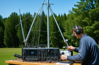
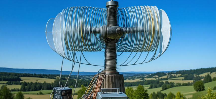
Structural Design Highlights
The antenna features a multi-element configuration reminiscent of a Yagi-Uda but with a novel twist: each element is adjustable in length and angle, allowing for fine-tuning across multiple amateur bands. Its modular segments can be repositioned or replaced easily, making maintenance straightforward and adaptable to different operational needs.
Innovative Features
- Multi-band capability: Covering 20m, 15m, and 10m bands with switchable elements.
- Artistic aesthetic: The antenna’s framework resembles a modern sculpture, integrating curves and symmetry.
- Weather resistance: Coatings and materials tailor-made to withstand harsh climatic conditions.
- Smart tuning mechanisms: Motorized adjustments controlled via a remote interface.
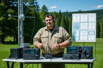
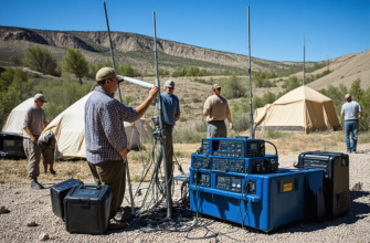
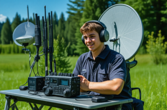
Installation Process
Site Selection
The chosen site was a spacious, elevated area with minimal obstructions, optimal for maximizing signal propagation. Careful assessment of surrounding structures and vegetation ensured minimal interference and optimal line-of-sight conditions.
Assembly Steps
- Foundation setup: Anchoring support structures with secure concrete bases.
- Framework assembly: Erecting the modular aluminum segments using stainless steel fittings.
- Radiator installation: Attaching the fiberglass elements and copper feed lines.
- Adjustment and alignment: Using a combination of protractors, laser levels, and software control to align elements precisely.
- Grounding and safety measures: Proper grounding wire installations to prevent static buildup and lightning strikes.
Testing and Tuning
Initial testing involved SWR (Standing Wave Ratio) measurements across bands. Fine-tuning was carried out by adjusting angles and lengths of elements, with the help of an antenna analyzer. The goal was to achieve SWR values below 1.5:1 for all targeted frequencies.
Performance Analysis and Results
Signal Gain and Directivity
Field measurements indicated a significant increase in gain compared to standard dipole and vertical antennas. The antenna demonstrated a highly directive pattern, focusing RF energy towards desired directions, thus enhancing long-distance communication capabilities.
Comparison Table of Performance Metrics
| Parameter | Standard Dipole | Conventional Yagi | Unique Antenna |
|---|---|---|---|
| Gain (dBi) | 2-3 | 8-12 | 10-13 |
| SWR across bands | Below 2:1 (average) | Below 1.5:1 (optimized) | Below 1.5:1 (after tuning) |
| Space occupied | ≈ 5 meters | ≈ 10 meters | ≈ 6 meters, with modular design |
| Operational bandwidth | Single band | Multiple bands (with traps) | Multiple bands, multi-element adjustable |
Lessons Learned and Practical Takeaways
Design Flexibility Is Key
Creating an antenna with adjustable elements proved invaluable. It allowed for iterative optimization without needing to dismantle the entire structure. Flexibility in the design led to better performance and easier maintenance.
Materials Matter
Durability and weather resistance are crucial for outdoor antennas, especially in severe climates. Selecting the appropriate materials ensures longevity and reduces ongoing costs.
Simulation Saves Time and Resources
Using advanced modeling software before physical construction minimized trial-and-error, resulting in a more efficient build process and predictable results.
Balancing Innovation and Practicality
While pushing technological boundaries is rewarding, grounding innovations with practical considerations—such as ease of tuning, maintenance, and cost—is essential for success in amateur radio endeavors.
Why This Antenna Is Truly Unique
The combination of innovative design, aesthetic appeal, and superior performance makes this antenna a standout example of amateur experimentation and ingenuity. It demonstrates that with creative thinking and precise engineering, even modest amateur radio setups can achieve extraordinary results. This project not only enhanced communication capabilities but also served as a catalyst for exploring new materials, design paradigms, and construction techniques.
For amateur radio operators looking to create their own unique antenna, the key lessons are to prioritize adaptability, pursue continuous learning, and embrace creativity. The journey of designing and installing such a remarkable antenna can be as rewarding as the signals it helps transmit across the airwaves.
References and Additional Resources
- ARRL Antenna Guides
- The ARRL Antenna Book
- Practical antenna construction tips
- Ham Radio Equipment and Components
Final Thoughts
In amateur radio, each antenna is a canvas for innovation. The journey from concept to installation, as recounted here, exemplifies the creativity and technical skill that define this hobby. Whether building a simple wire dipole or crafting a multi-element, multi-band masterpiece, the pursuit of better communication remains at the heart of every project. Dare to think outside the box, and your antenna might just become the most unique and effective tool in your radio arsenal.
Похожие записи:
 Innovative Antenna Designs for Enhanced HF Performance
 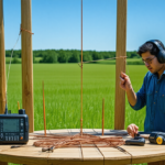 How to Build a Simple Dipole Antenna at Home: A Comprehensive Guide for Amateur Radio Enthusiasts
  Comprehensive Review of 3D Printing Solutions for Custom Radio Parts: Innovating Amateur Radio DIY Projects
  How a Simple Antenna Repair Sparked a Long-lasting Friendship – An Amateur Radio Journey
 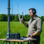 Mastering Your Amateur Radio Antenna: Comprehensive Guide to Tuning and Testing
 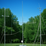 Basic Antenna Types and Their Uses for Beginners: A Comprehensive Guide for Amateur Radio Enthusiasts
  Building a Simple, Low-Cost Antenna Tuner at Home: A Comprehensive Guide for Amateur Radio Enthusiasts
 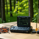 Portable Antenna Analyzers for Precise Tuning: The Ultimate Guide for Amateur Radio Enthusiasts
 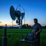 High-Gain Antennas for Long-Distance Communication: Unlocking Extended Reach in Amateur Radio
  The Time My Portable Station Surprised Everyone: A Spectacular Moment in Amateur Radio
  Building My First Transceiver and the Challenges Faced: An Amateur Radio Enthusiast’s Journey
  Reflecting on My First Homebrew Radio Project: A Journey into Amateur Radio
  Sharing the Story of My First Satellite Contact: An Amateur Radio Journey
 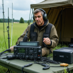 Mastering Your Amateur Radio Setup: Essential Guidelines for Field Day and Emergency Drills
  How to Build Your Own Homemade QRP Transceiver: A Comprehensive Guide for Amateur Radio Enthusiasts
 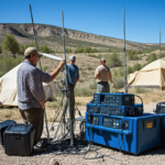 The Day I Helped Set Up a Remote Station for a Contest