For amateur radio enthusiasts, the antenna is the cornerstone of effective radio communication. An improperly tuned antenna can drastically reduce signal quality, limit transmission range, and create unnecessary interference. Proper tuning and testing are essential skills that ensure optimal performance, compliance with regulations, and a satisfying listening and transmitting experience.
This comprehensive guide covers all aspects of antenna tuning and testing, from understanding basic concepts to practical step-by-step procedures, equipment needed, troubleshooting common issues, and best practices for maintaining your antenna system. Whether you are a beginner or an experienced operator, this article aims to deepen your understanding and enhance your skills in managing your antenna system.
- Understanding the Basics of Antenna Tuning
- What Is Antenna Tuning and Why Is It Important?
- Key Concepts and Parameters
- Tools and Equipment Needed for Tuning and Testing
- Essential Instruments
- Step-by-Step Guide to Properly Tuning Your Antenna
- 1. Prepare Your Equipment and Environment
- 2. Establish a Baseline Measurement
- 3. Adjust the Physical Length of the Antenna
- 4. Fine-Tune for Minimized SWR
- 5. Record and Verify Results
- 6. Use a Vector Network Analyzer for Detailed Analysis (Optional)
- Calculating the Correct Antenna Length
- Basic Formula for Dipole Antennas
- Adjustments for Exact Tuning
- Testing Antenna Performance
- 1. Measuring SWR Across the Band
- 2. Confirming Resonance and Impedance
- 3. Propagation and Signal Quality Tests
- Common Troubleshooting Tips
- Best Practices for Maintaining Your Antenna System
- Regular Inspection and Maintenance
- Environmental Considerations
- Upgrading and Fine-Tuning Over Time
- Summary: Key Takeaways for Effective Antenna Tuning and Testing
Understanding the Basics of Antenna Tuning
What Is Antenna Tuning and Why Is It Important?
At the core, antenna tuning involves adjusting the antenna’s electrical length and configuration so that it efficiently radiates or receives radio frequency signals at a desired frequency or band. The key parameter in this process is the Standing Wave Ratio (SWR), which indicates how well the antenna is matched to the transmitter’s output impedance (typically 50 ohms).
When an antenna is not properly tuned, more power is reflected back into the transmitter, causing potential damage and reducing effective transmission distance. Additionally, poor tuning can lead to increased noise, interference, and reduced signal clarity.
Key Concepts and Parameters
- Impedance Matching: Ensuring the antenna’s impedance matches the transmitter’s output impedance for maximum power transfer.
- Standing Wave Ratio (SWR): The ratio of the amplitude of the forward wave to the reflected wave in the feedline. Ideal SWR is 1:1.
- Resonance: The frequency at which the antenna naturally oscillates with minimal reactance, leading to optimal performance.
- Reactance: The inductive or capacitive component of the antenna’s impedance; tuning aims to neutralize reactance at the operating frequency.
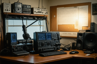
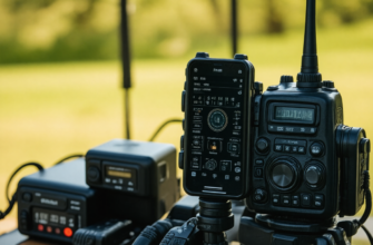
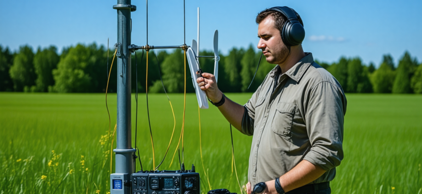
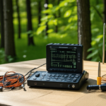
Tools and Equipment Needed for Tuning and Testing
Essential Instruments
| Instrument | Description | Purpose |
|---|---|---|
| SWR Meter | Device that measures SWR directly, often built into transceivers or as standalone units. | To monitor the SWR during tuning and testing. |
| Vector Network Analyzer (VNA) | Advanced instrument that measures impedance, SWR, and other parameters over a range of frequencies. | Precise tuning and detailed analysis of antenna characteristics. |
| Standing Wave Counter | Device that measures the number of standing waves on the feedline, indirectly indicating SWR. | Alternative to SWR meters for quick checks. |
| RF Signal Generator | Generates specific RF signals for testing antenna response. | Controlled testing and calibration. |
| Measuring Tape or Ruler | For physical adjustments of antenna length. | Physical tuning of antenna elements. |
| Insulating Material and Mounting Accessories | Insulators, brackets, etc. | Proper installation and adjustments. |
Step-by-Step Guide to Properly Tuning Your Antenna
1. Prepare Your Equipment and Environment
Ensure your transceiver, SWR meter, and any other necessary equipment are operational. Choose a clear location with minimal interference and a stable ground for installing the antenna. Take safety precautions, especially if working at heights or with high voltages.
2. Establish a Baseline Measurement
Connect the SWR meter between your transmitter and the antenna feedline. Turn on your transceiver and set it to the desired frequency band. Record the initial SWR reading. If SWR is excessively high (above 3:1), consider adjusting the antenna length or configuration before proceeding.
3. Adjust the Physical Length of the Antenna
Identify the adjusting points on your antenna (e.g., telescoping mast, adjustable elements). Use the measuring tape to modify the length according to the manufacturer’s specifications or calculated values based on wavelength (see below). Make small incremental changes to avoid overshooting.
4. Fine-Tune for Minimized SWR
- After each physical adjustment, transmit at the target frequency and observe the SWR reading.
- Refine the length until the SWR reaches its minimum, ideally close to 1:1 or at least below 1.5:1.
- Graph or record SWR readings at various frequencies if your antenna design allows for broadband tuning.
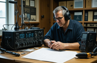
5. Record and Verify Results
Once optimal SWR is achieved at the desired frequency, document the exact length adjustments and SWR readings. Repeat the test at neighboring frequencies to ensure acceptable performance over the intended band.
6. Use a Vector Network Analyzer for Detailed Analysis (Optional)
If available, a VNA can provide detailed impedance plots across a range of frequencies, revealing reactance and resistance components. Use this data to make informed adjustments, particularly for complex or multi-element antennas.
Calculating the Correct Antenna Length
Basic Formula for Dipole Antennas
The approximate length of a half-wave dipole antenna can be calculated using the formula:
L (meters) = 143 / F (MHz)
Where:
- L – total length of the dipole (meters)
- F – frequency in MHz
For example, at 14.200 MHz (the 20-meter band):
- L = 143 / 14.2 ≈ 10.07 meters total, or about 5.04 meters per element.
Adjustments for Exact Tuning
Due to environmental factors, wire diameter, and installation height, practical tuning often requires slight modifications from theoretical calculations. Always verify with SWR measurements.
Testing Antenna Performance
1. Measuring SWR Across the Band
Use an antenna analyzer or SWR meter to plot the SWR across the entire frequency range of interest. Aim for a low SWR (below 1.5:1) across as broad a bandwidth as possible, especially for multi-band antennas.
2. Confirming Resonance and Impedance
A vector network analyzer can help ensure the antenna is resonant at the operating frequency and that the impedance is close to 50 ohms. Reactance should be near zero at resonance.
3. Propagation and Signal Quality Tests
Perform actual radio contacts to evaluate how well the antenna transmits and receives signals. Use reports from contacts, signal reports, and audio quality as practical indicators of antenna performance.
Common Troubleshooting Tips
- High SWR persists: Check for physical damage, poor connections, or incorrect length adjustments.
- Rain or humidity impacts SWR: Ensure insulators and feedline connectors are dry and intact.
- Unexpected interference: Confirm that nearby objects, such as metal structures or other antennas, are not detuning your setup.
- Continuously high SWR across bands: Consider using antenna matching devices like antenna tuners or loading coils.
Best Practices for Maintaining Your Antenna System
Regular Inspection and Maintenance
Inspect the physical integrity of the antenna, connectors, and grounding systems periodically. Clean connectors and replace worn insulators or damaged wire sections to maintain optimal performance.
Environmental Considerations
Secure the antenna against strong winds and weather conditions. Use waterproof and corrosion-resistant materials, especially for outdoor installations.
Upgrading and Fine-Tuning Over Time
As your operating environment changes or your needs evolve, revisit tuning procedures. Consider experimenting with antenna modifications or adding matching devices to improve broadband performance.
Summary: Key Takeaways for Effective Antenna Tuning and Testing
- Understanding and properly measuring SWR is crucial for efficient antenna operation.
- Follow manufacturer specifications and use appropriate tools to achieve optimal tuning.
- Adjust antenna length physically, then verify and fine-tune with measurement devices.
- Use advanced equipment like a vector network analyzer for detailed analysis.
- Regularly inspect and maintain your antenna setup to ensure consistent performance.
Effective tuning and testing of an amateur radio antenna are fundamental skills that significantly influence operational success and signal quality. While theoretical calculations provide a good starting point, practical adjustments and measurements ensure your antenna performs optimally in its specific environment. Patience, meticulous measurement, and maintenance will pay off with clearer signals, extended range, and more enjoyable communication experiences across the amateur radio community.
Mastering these techniques empowers amateur radio operators not only to improve their station’s performance but also to deepen their understanding of radio physics and engineering principles.
Похожие записи:
 Portable Antenna Analyzers for Precise Tuning: The Ultimate Guide for Amateur Radio Enthusiasts
 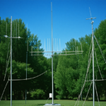 Basic Antenna Types and Their Uses for Beginners: A Comprehensive Guide for Amateur Radio Enthusiasts
  Building a Simple, Low-Cost Antenna Tuner at Home: A Comprehensive Guide for Amateur Radio Enthusiasts
 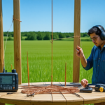 How to Build a Simple Dipole Antenna at Home: A Comprehensive Guide for Amateur Radio Enthusiasts
 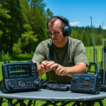 Portable Spectrum Analyzers for Field Frequency Testing: A Complete Guide for Amateur Radio Enthusiasts
 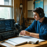 Mastering Regulatory Changes: A Comprehensive Guide for Amateur Radio Enthusiasts
  How to Build Your Own Homemade QRP Transceiver: A Comprehensive Guide for Amateur Radio Enthusiasts
  Understanding Ham Radio Frequencies and Bands: A Comprehensive Guide for Amateur Radio Enthusiasts
 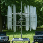 Innovative Antenna Designs for Enhanced HF Performance
  Mastering DXing: Expert Tips for Contacting Rare Amateur Radio Stations
 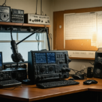 Ultimate Guide: Tips for Setting Up Your Home Radio Station
  Integrating Software-Defined Radio into Your Daily Operations: A Comprehensive Guide for Amateur Radio Enthusiasts
 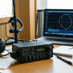 Top Choices for Budget-Friendly Amateur Radio Equipment: A Comprehensive Guide for Hobbyists
 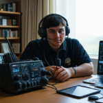 Mastering Digital Voice Conferences: How to Participate Effectively in the Modern Amateur Radio Era
 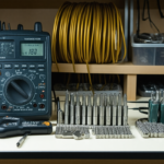 Essential Tools for Cable and Connection Maintenance: A Complete Guide for Amateur Radio Enthusiasts
  Effective Troubleshooting Guide for Common Radio Hardware Issues in Amateur Radio