Building a QRP (low-power) transceiver at home is an exciting project that combines technical skill, creativity, and a passion for radio communication. Whether you are an experienced amateur radio operator or a newcomer eager to dive into the world of DIY electronics, crafting your own transceiver offers both educational value and an unmatched sense of achievement. In this detailed guide, all aspects of designing, assembling, and troubleshooting a homemade QRP transceiver will be covered, providing a step-by-step roadmap for hobbyists who wish to develop a compact, efficient, and reliable radio station from scratch.
- Introduction to QRP Transceivers
- Understanding the Basic Principles of QRP Transceiver Design
- Core Components and Their Roles
- Design Goals for a Homemade QRP Transceiver
- Choosing the Right Electronics and Materials
- Component Selection
- Tools and Supplies Needed
- Designing Your QRP Transceiver Circuit
- Creating the Block Diagram
- Sample Block Diagram Components
- Understanding Frequency Planning
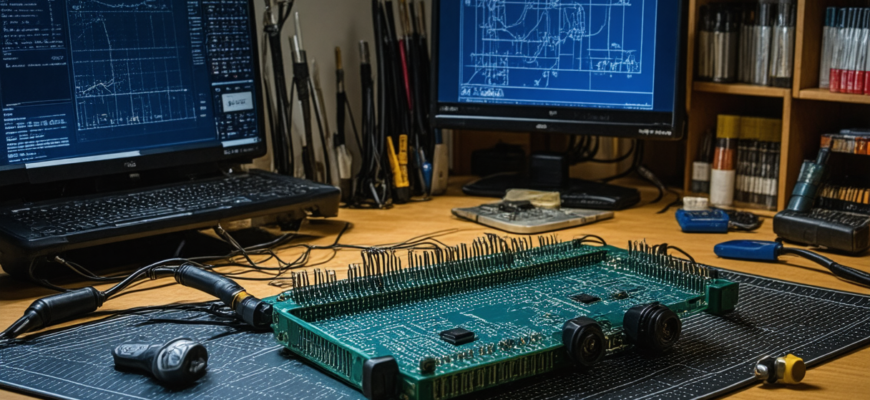
- Step-by-Step Construction Guide
- 1. Building the VFO
- 2. Designing the Mixer and Frequency Conversion
- 3. Developing the RF Amplifier Stage
- 4. Implementing the Modulation Circuit
- 5. Assembling the Power Amplifier
- 6. Building the Receiver Front-End
- 7. Integrating the Controls and Tuning Mechanisms
- 8. Final Assembly and Enclosure
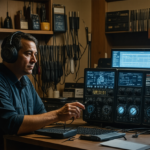
- Testing and Calibration
- Initial Power-Up and Troubleshooting
- Frequency Calibration
- Power Output Measurement
- An example table of calibration steps:
- Additional Tips for Success
- Advanced Topics and Improvements
- Digital Signal Processing (DSP)
- Software-Defined Radio (SDR) Approaches
- Power Efficiency and Portability
Introduction to QRP Transceivers
QRP operation refers to transmitting with low power, typically between 1 to 5 watts. Such transceivers are favored for their simplicity, portability, and energy efficiency. They are ideal for portable operations, emergency communication, or just the joy of building a compact radio device. Although limited in range compared to higher power stations, QRP transceivers challenge builders and operators to maximize performance within minimal power constraints.
Understanding the Basic Principles of QRP Transceiver Design
Core Components and Their Roles
An effective QRP transceiver contains several fundamental components:
- Power Amplifier: Boosts the RF signal to the desired transmission power.
- Mixer and Local Oscillator (LO): Converts frequencies for transmission and reception, enabling single-sideband (SSB) or amplitude modulation (AM).
- VFO (Variable Frequency Oscillator): Provides tuning capability for selecting frequency bands.
- Receiver Front-End: Includes filters, preamplifiers, and detectors for signal processing.
- Transmitter Front-End: Incorporates modulation circuits, buffers, and power stages.
- Power Supply: Provides stable voltage for all circuitry, often a battery or regulated power source.
Design Goals for a Homemade QRP Transceiver
While constructing a home-made QRP transceiver, it’s essential to define clear objectives:
- Compact size and portability
- Ease of assembly and troubleshooting
- Reliable and stable operation
- Good selectivity and sensitivity
- Cost-effectiveness
Choosing the Right Electronics and Materials
Component Selection
Building a transceiver requires selecting appropriate electronic components. Prioritize quality and availability, especially for critical parts like the oscillator and RF transistors or ICs.
| Component Type | Recommended Specifications | Examples |
|---|---|---|
| Transistors/ICs | RF-grade, low noise, high gain | 2N3904, 2N2222, SA612, NE602 |
| Capacitors | Electrolytic for bulk, ceramic for high frequency | 100nF, 10uF electrolytic |
| Inductors | Low resistance, adjustable for tuning | Air-core coils, ferrite beads |
| Resistors | Specify power rating, precision | 1kΩ, 10kΩ, 100Ω |
| Filters | Bandpass filters for selectivity | LC filters, ceramic filters |
Tools and Supplies Needed
- Soldering iron and solder
- Multimeter
- Oscilloscope (optional but helpful)
- PCB or perfboard for assembly
- Enclosure case
- Connecting wires and connectors
- Power supply or rechargeable batteries
Designing Your QRP Transceiver Circuit
Creating the Block Diagram
Before jumping into circuits, sketch a block diagram. It helps visualize how components connect and facilitates adjustments.
Sample Block Diagram Components
- VFO Module → Mixer → IF Filter → Demodulator (receiver)
- Microphone → Modulator → Mixer → Power Amplifier → Antenna
Understanding Frequency Planning
Select a desired amateur radio band, such as 40m (7 MHz) or 20m (14 MHz). Plan the local oscillator frequency and filters accordingly. For example, for 40m operation, the VFO should cover approximately 7 MHz, with intermediate frequency (IF) stages tuned to specific values (e.g., 455 kHz).
Step-by-Step Construction Guide
1. Building the VFO
Start with the oscillator circuit, which can use logic chips, quartz crystals, or varactor diodes for tuning. A common choice is a Colpitts oscillator with a variable capacitor or varactors for fine tuning.
2. Designing the Mixer and Frequency Conversion
The mixer combines the VFO signal with incoming RF signals or generates the transmitted frequency. Use high-performance diodes or transistor-based mixers like the NE602 or SA612.
3. Developing the RF Amplifier Stage
This stage amplifies the RF signal before transmission, ensuring sufficient power output. Use RF transistors like the 2N2222 or specialized RF power transistors if higher power output is desired.
4. Implementing the Modulation Circuit
For voice or data modulation, integrate a microphone preamp, amplitude modulation (AM), or single sideband (SSB) circuits. Modern projects often use software-defined modules or simple analog modulation circuits.
5. Assembling the Power Amplifier
Design a stage capable of delivering the desired power (1-5W), using appropriate transistors and heat dissipation measures. Include biasing circuits to ensure linear operation and efficiency.
6. Building the Receiver Front-End
Incorporate bandpass filters to isolate your frequency band, low-noise RF transistors, and detectors for demodulation. Adequate shielding reduces interference and improves sensitivity.
7. Integrating the Controls and Tuning Mechanisms
Install tuning potentiometers, switches, and indicator LEDs or meters for status monitoring. Use multi-turn potentiometers for precise adjustments.
8. Final Assembly and Enclosure
Ensure all circuits are securely mounted inside an enclosure, with proper venting and labeling. Use RF-shielded cases to prevent external interference.
Testing and Calibration
Initial Power-Up and Troubleshooting
Begin with a low power test, verifying power supply voltages, and checking for shorts or cold solder joints. Use a multimeter to confirm component values and connections.
Frequency Calibration
Connect a frequency counter or receiver to measure output frequency. Adjust the VFO coil or varactors for accurate tuning.
Power Output Measurement
Use a dummy load or wattmeter to measure the RF power output. Use minimal power settings initially to prevent damage.
An example table of calibration steps:
| Step | Description |
|---|---|
| 1 | Power on the transceiver, verify voltages |
| 2 | Adjust VFO for the desired frequency using a frequency counter |
| 3 | Test modulation quality and sound clarity |
| 4 | Measure RF output power and adjust bias as needed |
Additional Tips for Success
- Start with a simple design and gradually add complexity
- Use high-quality, shielded cables to prevent interference
- Document each modification and measurement for future reference
- Join online forums or local ham radio clubs for advice and shared experience
- Respect legal limits and regulations regarding transmission power and frequency bands
Advanced Topics and Improvements
Digital Signal Processing (DSP)
Incorporate DSP modules for filtering, noise reduction, or even digital modes like FT8 or PSK31, expanding the capabilities of your homemade transceiver.
Software-Defined Radio (SDR) Approaches
Utilize microcontrollers or FPGA chips for generating and decoding signals, allowing for more precise control and features without extensive analog circuitry.
Power Efficiency and Portability
Use rechargeable batteries, low-power components, and efficient regulators to extend operational time and ease of transport for portable operations.
Building a custom QRP transceiver at home is a rewarding project that enhances understanding of radio principles, electronics, and practical construction techniques. While challenges are inevitable in such complex DIY endeavors, the knowledge gained and the satisfaction of operating a self-built radio station outweigh the effort. By following structured design principles, selecting quality components, and maintaining meticulous testing practices, amateur radio enthusiasts can create reliable, effective, and compact transceivers tailored to their specific interests. Whether for casual ham radio activities or emergency communication preparedness, homemade QRP transceivers represent both a technical achievement and a personal milestone in the vibrant world of amateur radio.
Похожие записи:
 Effective Troubleshooting Guide for Common Radio Hardware Issues in Amateur Radio
 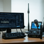 Ultimate Guide: Best Practices for Setting Up a Remote Radio Station Accessible Worldwide
 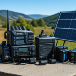 Advances in Battery Technology for Portable Ham Radio Use: Powering the Future of Amateur Radio
 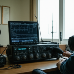 New Regulations Affecting Amateur Radio Licensing and Operation: What You Need to Know
 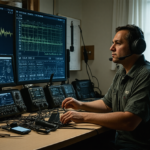 Emergency Communication Protocols for Ham Radio Operators: The Latest Updates and Best Practices
 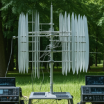 Innovative Antenna Designs for Enhanced HF Performance
  Последние достижения в области цифровых средств связи в любительском радио: инновации и будущее