For amateur radio hobbyists, understanding how antennas radiate signals into the environment is fundamental to optimizing communication performance. The concepts of antenna mapping and radiation patterns play a crucial role in designing and positioning antennas effectively. This comprehensive guide explores the principles behind antenna radiation characteristics, how they can be visualized and mapped, and practical applications for amateur radio operators.
- Introduction to Antenna Radiation Patterns
- What Are Radiation Patterns?
- Definition and Significance
- Types of Radiation Patterns
- Understanding Antenna Gain and Directivity
- Relation Between Gain, Directivity, and Efficiency
- Visualizing Radiation Patterns
- Polar Plots and Pattern Charts
- Example of a Typical Radiation Pattern
- How to Measure Antenna Radiation Patterns
- Tools and Equipment Needed
- Measurement Procedure
- Understanding Antenna Mapping
- What Is Antenna Mapping?
- Methods of Antenna Mapping
- Optimizing Antenna Placement Using Mapping Data
- Impact of Surroundings
- Practical Steps for Effective Placement
- Case Study: Improving Performance of a Yagi Antenna
- Formulas and Calculations Related to Antennas
- Directivity Formula
- Beamwidth and Its Significance
- Practical Tips for Amateur Radio Enthusiasts
- The Future of Antenna Mapping in Amateur Radio
Introduction to Antenna Radiation Patterns
Every antenna, when transmitting or receiving radio waves, exhibits a specific pattern of radiation in space. This spatial distribution is known as the antenna’s radiation pattern. It describes the relative strength of the radio waves emitted or received in different directions around the antenna. Understanding these patterns allows operators to maximize signal strength toward desired directions and minimize interference from unwanted sources.
What Are Radiation Patterns?
Definition and Significance
Radiation patterns are graphical representations of the electromagnetic power radiating from an antenna as a function of direction. These patterns are invaluable for visualizing an antenna’s directivity, gain, and beamwidth. They inform where to orient the antenna for optimal performance and how to position multiple antennas for diverse communication needs.
Types of Radiation Patterns
- Omnidirectional Patterns: These antennas radiate equally in all horizontal directions, typical of vertical monopole antennas used in mobile or base stations.
- Directional Patterns: These radiate more power in specific directions, enhancing signal strength toward targets. Examples include Yagi, dish, and log-periodic antennas.
- Isotropic Pattern: A hypothetical ideal antenna that radiates equally in all directions; used as a reference for measuring real antenna gain.
Understanding Antenna Gain and Directivity
Gain is a critical parameter in antenna performance, defined as the ability to focus energy in specific directions compared to an isotropic radiator. The higher the gain, the more concentrated the signal will be in certain directions, resulting in increased effective communication distance.
Relation Between Gain, Directivity, and Efficiency
| Parameter | Definition |
|---|---|
| Gain (G) | Overall measure of how well an antenna directs radio energy in a particular direction, including efficiency factors. |
| Directivity (D) | Theoretical measure of the antenna’s ability to concentrate energy in a specific direction, assuming 100% efficiency. |
| Efficiency (η) | The ratio of radiated power to input power, indicating how effectively the antenna converts input energy into radiated electromagnetic waves. |
Relationship among these parameters can be expressed as:
G = D × η
Visualizing Radiation Patterns
Polar Plots and Pattern Charts
Radiation patterns are commonly visualized as polar plots, where the distance from the center indicates relative signal strength in that direction. These plots can be obtained through measurement or simulation and often show both horizontal and vertical planes. Interpreting these charts allows amateur radio operators to fine-tune their antenna orientations.
Example of a Typical Radiation Pattern

How to Measure Antenna Radiation Patterns
Tools and Equipment Needed
- Signal generator or transmitter with known power output
- Receiving antenna or probe
- Rotator to change antenna orientation
- RF power meter or spectrum analyzer
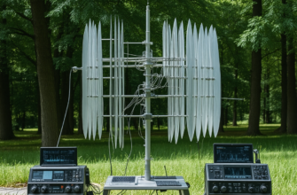
- Array of measurement points in space (using a test range or field
Measurement Procedure
- Set up the transmitting antenna at a fixed point with stable power output.
- Place the receiving antenna at a consistent distance, typically several wavelengths away to ensure far-field conditions.
- Rotate the antenna in azimuth and elevation angles, recording the received signal strength at each position.
- Plot the collected data on a polar chart to visualize the pattern.
Understanding Antenna Mapping
What Is Antenna Mapping?
Antenna mapping is the process of creating a detailed, spatial representation of an antenna’s radiation characteristics. It involves measuring signal strength in multiple directions and constructing a comprehensive visual or numerical model. This helps operators understand where their antenna performs best and how environmental factors may influence performance.
Methods of Antenna Mapping
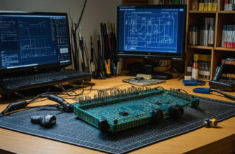
- Field Measurements: Conducted outdoors with specialized measurement gear.
- Simulation Software: Using electromagnetic modeling tools such as NEC (Numerical Electromagnetics Code) or EZNEC to predict radiation patterns virtually.
- Hybrid Approaches: Combining field data with simulations for precise analysis.
Optimizing Antenna Placement Using Mapping Data
Impact of Surroundings
Buildings, trees, terrain, and other obstacles can distort radiation patterns. By mapping an antenna’s performance around its installation site, operators can identify the optimal orientation and height to minimize interference and maximize gain toward desired communication paths.
Practical Steps for Effective Placement
- Map the existing radiation pattern of the antenna in situ.
- Identify directions with the strongest signal—these are ideal for targeting distant stations.
- Adjust azimuth and elevation to concentrate coverage in desired directions.
- Monitor changes over time, especially if environmental conditions or nearby structures evolve.
Case Study: Improving Performance of a Yagi Antenna
Consider an amateur operator using a Yagi antenna for long-distance HF communications. Initial measurements reveal that the radiation pattern is slightly skewed due to nearby structures. By mapping the pattern in situ, the operator notices a side lobe that reduces gain toward a particular region. Adjusting the antenna’s orientation and height, guided by the mapping data, results in a more focused and effective signal pattern, substantially improving contact success with distant stations.
Formulas and Calculations Related to Antennas
Directivity Formula
The directivity (D) of an antenna can be approximated as:
D = 4π / Ω
where Ω is the solid angle in steradians over which the antenna radiates power significantly.
Beamwidth and Its Significance
The Half Power Beamwidth (HPBW) defines the angular width of the main lobe at which the radiated power drops to half (-3 dB) of its maximum. Smaller beamwidths correspond to more focused, directional antennas.
- Approximate relation:
HPBW ≈ 70° / (antenna length / wavelength)
Practical Tips for Amateur Radio Enthusiasts
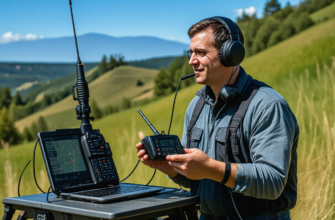
- Conduct Regular Measurements: Periodic mapping ensures optimal performance and detects environmental changes.
- Use Reliable Equipment: Accurate RF meters and rotators improve measurement quality.
- Simulate Before Deployment: Use modeling software to predict or refine radiation patterns prior to physical setup.
- Document and Share Results: Keep detailed records of antenna configurations and mappings to facilitate future adjustments or community sharing.
The Future of Antenna Mapping in Amateur Radio
Advancements in portable measurement tools, software simulations, and data sharing platforms have made antenna mapping more accessible to amateurs. Integrating GIS (Geographic Information Systems) and real-time environmental data can further enhance antenna deployment strategies, leading to better communication quality and innovative station setups.
Understanding the principles of antenna mapping and radiation patterns is essential for optimizing amateur radio communications. Through careful measurement, analysis, and adjustment based on detailed radiation patterns, operators can improve signal quality, increase range, and avoid interference. Whether utilizing traditional measurement techniques or advanced simulation tools, mastering these concepts empowers enthusiasts to take their radio skills to new heights and enjoy more reliable, efficient communication worldwide.
Похожие записи:
 Basic Antenna Types and Their Uses for Beginners: A Comprehensive Guide for Amateur Radio Enthusiasts
  How to Build a Simple Dipole Antenna at Home: A Comprehensive Guide for Amateur Radio Enthusiasts
  Innovative Antenna Designs for Enhanced HF Performance
  Revolutionizing Amateur Radio: How a New Antenna Design Transformed My Station
  Portable Antenna Analyzers for Precise Tuning: The Ultimate Guide for Amateur Radio Enthusiasts
  Building a Simple, Low-Cost Antenna Tuner at Home: A Comprehensive Guide for Amateur Radio Enthusiasts
  Understanding Ham Radio Frequencies and Bands: A Comprehensive Guide for Amateur Radio Enthusiasts
  Understanding Your Radio’s Firmware and How to Update It: A Comprehensive Guide for Amateur Radio Enthusiasts
  Mastering Your Amateur Radio Antenna: Comprehensive Guide to Tuning and Testing
  The Most Unique Antenna I Have Ever Installed: A Deep Dive into Innovative Amateur Radio Solutions
  Get Ready for the Upcoming 10 Meter Contest: The Ultimate Guide for Amateur Radio Enthusiasts
  How to Build Your Own Homemade QRP Transceiver: A Comprehensive Guide for Amateur Radio Enthusiasts
 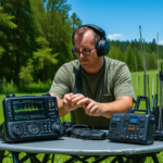 Portable Spectrum Analyzers for Field Frequency Testing: A Complete Guide for Amateur Radio Enthusiasts
 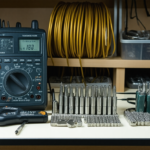 Essential Tools for Cable and Connection Maintenance: A Complete Guide for Amateur Radio Enthusiasts
  Effective Propagation Analysis Techniques Throughout the Year: Maximizing Ham Radio Performance
  Mastering Regulatory Changes: A Comprehensive Guide for Amateur Radio Enthusiasts